Phenom Engineering
Connect With Us
  • Home
    • Store - Mill
    • Store - Lathe
  • Services
  • Blog
  • About
  • Contact
  • Shipping
  • Photos and Videos

Lean Tools: Part 1 - The Spaghetti Diagram

8/13/2017

2 Comments

 
​In my career, I’ve been lucky enough to work established defense industry programs as well as starting up new products and factories.  This has given me many opportunities to see problems and do something to fix them.  I’ve used many Lean tools over the course of my career and I would like to explore these tools with real world examples of how they were applied and the results they produced.

The first of this (hopeful) series will look at the spaghetti diagram.  In its simplest terms, a spaghetti diagram is a visual representation of how people or processes move in a factory or work cell.  Specifically, it is how the process happens in reality, not how the process is supposed to work or how an ideal process happens.  So this means going out to the floor and watching and recording what happens on a paper layout of the work space.
I recently was responsible for the layout of a production process for a $7.0 million (each!) space vehicle in a brand new facility.  I had worked the same product in the original production facility, which allowed me to benchmark the current process.  Since I was responsible for all aspects of production in the new facility (tooling, training, metrics, layout, facilitization, etc.) I could take the benchmark data from the original facility and make the improvements I thought necessary in the new factory.  This also meant I had an apples to apples comparison of the improvement from the old process to the newly optimized method.
​
The original factory was set up in an explosives production area due to the rocket motors involved (class 1.3 explosives).  Typically, a facility that handles explosives is set up in ‘bays’.  These bays are built with concrete walls separating them and a frangible, blow out wall to release the overpressure of an inadvertent explosion or rocket motor ignition.   This set up also meant inefficiencies, as is evident by the spaghetti diagram of the original process.
Picture
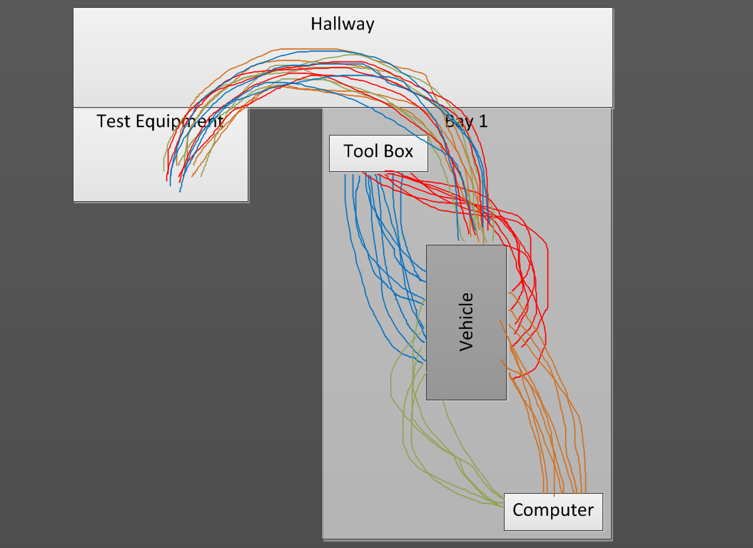
Figure 1. Original process and layout.
​With the original process, there was a lot of wasted motion.  The bays were too big for the product being assembled and the nature of the bay meant it was isolated from the other production areas.  Operators moved many feet from the product to the tool rack and back.  The test equipment was set up in a separate bay, meaning the operators had to move the vehicle to the test equipment and back - twice.  The instructions used to do the work were located on a computer against a wall.  The operators were constantly in motion, and due to the layout and the available material handling tools, more operators were required to do the work.  The spaghetti diagram highlighted just how much motion was wasted moving from the vehicle to the computer or the tool rack.
​
In the new facility, I changed basically every part of the process, following a lean methodology.  The factory work cell layout was changed from the bay style to a true ‘U’ cell layout.  All new tooling was developed to increase efficiency.  The build orientation of the vehicle was changed to remove time consuming and dangerous material lifts.  The test equipment was brought to the cell, instead of taking the vehicle to the test equipment.  Tool boxes and computers were located such that the operator only had to take one step left or right to get a tool or enter data in the computer.  
Picture
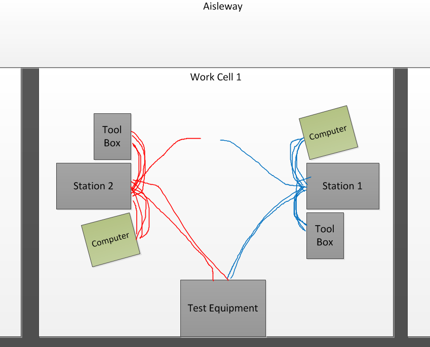
Figure 2. Redesigned process and layout.
​​In the end, efficiency, safety and cycle time were all greatly improved.  What took 5 operators 4.5 days to build in the old factory, was now being accomplished in 2.5 days with only 2 operators.  It used to take 180 man hours to build the vehicle; the new process dropped that to 40 man hours!  That equates to a 77% reduction in touch labor charges per vehicle.  Using a spaghetti diagram of the original set up allowed us to visualize the process and highlight the areas in need of improvement.  After making changes, revisiting the spaghetti diagram for the new process provided a measurement of ‘goodness’ for the new process.  Keeping in the spirit of Kaizen, the spaghetti diagram of the new process will also help inform changes for the future to help make the process even more lean and efficient. 
2 Comments

Mini lathe project: chuck key safety switch

5/25/2016

1 Comment

 
Add a place to keep your chuck key and throw in some safety for good measure!
Chuck Key Holder
Turning on a lathe with the key in the chuck is a easy way to get a trip to the hospital. A flying key can easily put a hole in your wall or break your nose. Every time I turn on the lathe, I'm reminded of working in the ASU machine shop on my capstone project and the machine shop lead pointing to a hole in the wall above the door leading to the shop: “See that hole? Someone left the key in the chuck. Not only did it put a hole in the wall, but someone was walking through the door at the time. It could have hit them in the face. Don't ever take your hand off the key while it's in the chuck.”

It's no surprise, then, that the first tool I purchased for the lathe was a self-ejecting key (a chuck key with a spring around the shaft to force it out of the chuck when you let go of it). This key is great, but I still needed a place to keep it. Being a proponent of lean manufacturing, I have to have a place to keep the key so I always know where it is. I kept it resting across the housing of the lathe and the end of the chuck shield hardware (the chuck shield was the first thing to be removed from the lathe, since the chuck key ejects automatically).

The standard chuck shield safety switch included with most mini lathes uses a microswitch with a small pin and an indented disk to operate. This circuit is required for the lathe to turn on. The controller board verifies that there is voltage across pins 6 and 7 on the board. The microswitch is wired as normally closed, so that when the pin is not activating the switch, the circuit is completed. If that circuit is open, the lathe will not turn on.

My original intention was to remove the chuck shield hardware altogether, but, as mentioned before, a closed circuit condition is required for the lathe to run. I could have simply shorted (jumped) the pins to make it work, but why not put that switch to good use? Even if I can't leave the key in the chuck, I can still use the switch to ensure the key is always put back where it belongs, therefore giving the key a standard place to live. I also wanted to use only hardware that came from the removal of the chuck safety shield to keep costs to a minimum. This allows for the reuse of the wires, switch and screws. This also means that I can reuse the original mounting location.

Lathe Chuck Key Holder
The result was a small plastic block that mounts to the back of the lathe housing. There is a large through hole which holds the key. It has a chamfered lead in on each end to help get the key out of the holder without getting hung up. The microswitch sits in a pocket next to the shaft of the key; it is activated by the handle of the key as it sits in the holder. The holder is secured to the lathe housing using the two removed screws into the same mounting location. The wires exit the housing in the same direction and location as the original safety switch.

The whole system works great. The chuck key reliably engages the switch when dropped into the holder, thanks to the two chamfered lead-ins. The key doesn't get hung up in the holder when putting it in or removing it. Plus, the switch in the housing means the key is always put back where it belongs!

​Want to add this upgrade project to your mini lathe? We've got you covered: You can get the .stl file here for free (scroll down for the downloadable file) and 3D print it if you own a printer, you can have it printed by the 3D printing service of your choice, or you can purchase the printed holder from our site. Full installation instructions with pictures are included below (keep scrolling for a downloadable pdf).  

NOTE:  These instructions are provided for informational purposes only.  As such, we hold no liability if you should injure yourself/others or damage your equipment.  The provided files are for personal use only and thus are not for commercial use without the express written consent of Phenom Engineering, LLC.

Picture

Installation Instructions:

Download a copy:
chuck_safety_switch_instructions.pdf
File Size: 795 kb
File Type: pdf
Download File

1 Comment

Introducing the All new PhotonX2!

3/30/2016

3 Comments


Next Generation of our popular spindle light

Picture
The PhotonX2 was designed from the ground up to solve the lighting issues inherent with the design of the Sieg X2 milling machine.  The head of the mill is large and always the same distance from the tool, meaning that it always gets in the way of overhead lights and floor/desk lamps.  

This latest generation of PhotonX2 (generation 3) is all new from the inside out.  The housing has been redesigned to hold a 80mm COB (more on this later) LED ring light and larger magnets.  The magnets still remain on the original 2.82" diameter but are larger and provide about 30% more holding force than the original.  With the increase in size of the LED ring, this has allowed us to open up the inner diameter of the housing, meaning it can fit a much larger spindle.  The new max spindle OD is 2.25", vs. the original 1.875".  This will allow for use on more machines than just the X2 series.  The wire cable is simplified; no longer requiring modification, making it easier to produce.  The spring-back (retractile) coils of the original cable have been removed in favor of providing more length to grant a wider range of mounting options.  A short length of shrink tubing provides the rigidity needed to keep the cable out of the way.  The rocker switch has also been replaced by a rotary switch to allow for control of the brightness of the light.  In addition, there is the option to replace the rotary switch with a RF remote to allow for ON-OFF and brightness control without having to reach across the bed to turn on the light!   This next generation design has been in the works for months, and when we say it is all new, we really mean it!  

The PhotonX2's increase in size makes for a more versatile unit, meaning it can fit many more applications than just the X2.  The dimensions of the unit are: outer diameter: 3.50", inner diameter: 2.30" and a thickness of 0.78".  The magnets that hold it to the milling head are on the same diameter as the original.  This means the PhotonX2 will fit any mill that has a spindle diameter of 2.25" or less and a magnetic mounting surface of at least 2.90".  This covers most mills including Bridgeport/clones.
Picture

so, how bright is the new PhotonX2?

Picture
In the new version of the PhotonX2, we used a 80mm LED ring, an increase from the original 70mm.  In addition to the larger diameter, we changed from the standard 1210 SMD LED to the new COB (chip on board) design, which is the latest in LED technology.  The main benefit of this new design is light density; with the resistors moved off the circuit board, there is more room for LED elements.  The 70mm 1210 package had 21 LEDs on it.  The 80mm COB design has 93!  What this means is more light, projected more evenly!

The higher LED density means this is now the brightest mini mill spindle light we have ever made.  Notice, our product shots are with the shop with lights ON.  The ambient light at the vise is 105 lux.  With the PhotonX2 on, the average light output 5 inches directly under the spindle is about 2,500 lux!  This level of illuminance is normally seen where maximum visual acuity is required, such as in precision assembly or detailed drafting.  To ensure you get just the right amount of light you need, the PhotonX2 comes with a ON-OFF rotary switch, which allows you to adjust the brightness of the spindle light.  There will also be an option to upgrade to a RF remote, allowing you to turn the light on and off and control the brightness remotely! 

Picture
So, what does this mean when you are actually making chips?  Let's start off with an end mill in a collet.  If you were taking a cut off the top surface of a piece of stock, the bottom of the spindle would be about 1.75" above the top of the vise.  The illuminance of the workpiece in this situation would be about 6,640 lux!  That is the level of lighting you would expect for the most demanding of precision assembly tasks.

Now, let's look at what happens when you have a drill chuck in the spindle.  Due to the size of the body of the chuck, most of the direct light is blocked.  We've developed formulas to determine the diameter of a light ring that is needed to clear a chuck with various drill bit lengths.  The function is exponential, with the required diameter growing excessively large in short order.  With the end of the input shaft protruding from the bottom of the head on the X2 mill and the overall size of the milling head, the diameter of the light is limited.  With the PhotonX2, the illuminance directly under the chuck is about 220 lux.  While this is low compared to the example above, this number is still about 110% more than the ambient lighting in the shop.  As you can see in the graph, the illuminance goes up as you get away from the center.
Picture
As with our previous versions, the PhotonX2 comes with everything you need to install and use the unit.  In the package will be a 12v power adapter, the adjustable switch, a fully assembled spindle light, cable mounts and zip ties.  Installation is easy, as all you have to do is stick the spindle light to the milling head, route and secure the cables as you would like and plug in the power supply.  You will be ready to make chips in just a few minutes!
3 Comments

Celebrating the territorial cup returning to asu (2015)

11/30/2015

4 Comments

 
Picture
After graduating from Arizona State University with a bachelor's degree in mechanical engineering in 2008, I moved into the heart of rivalry territory (Tucson) to work for a defense company.  I constantly have to endure the tortuously unoriginal ASU jokes ("ASWho??" - wow, really inventive!) and the backhanded compliments from the UofA bandwagon fans in the office.  Needless to say, the ASU/UofA football game (the Duel in the Desert) is a very important game for us in the office.  It gives one side a leg up on the arguments for the following year, until the next match up.

Starting in 1899, the two teams met to play one game for territorial bragging rights and the trophy, the Territorial Cup.  This meeting would continue on a semi regular basis for the next several decades, until 1946 when it became an annual match up.  In 2001, the trophy would start changing hands, being displayed at the school that won that year's game.  The Territorial Cup is the oldest rivalry trophy in college football.

In honor of ASU bringing the Territorial Cup back to Tempe this year, we 3D printed our own desk sized version of the cup.  After receiving a significant amount of interest about the cup on social media, we decided to offer it for sale for a limited time.  The cup measures 4" tall and is about 4.25" wide at the handles.  While it is functionally a cup, it is not food safe.  Now, just in case: for legal reasons, this is not a direct replica, but a cup of our own design modeled after the Territorial Cup, with some changes made to give it the best chance of being 3D printed.  

There are two versions available: 
1. A 3D printed cup made in our shop using our FFF (fused filament fabrication) printer.  This printer builds the cup by squirting molten plastic through a nozzle one layer at a time.  This is a slow process and will take about 8 and a half hours to complete.  Parts made using this printing process are functional, but the surface finish is rough and will show some delamination of the layers due to the uneven cooling of such a large part (see pictures).  This is the cheapest option and is available in our store.  Depending on the number of orders received, I expect to ship the cups within 3 days of an order being placed.  

Picture
Picture
2. A 3D printed cup from a professional print house using SLS (selective laser sintering).  This process also builds a part layer by layer but uses a laser to melt plastic and fuse the powder particles together.  Parts made using this printing process are functional with a nice surface finish (see picture below).  This option is more expensive and is available through our Shapeways shop.  They will print and ship directly from their facility to you.  This normally takes about 10 days.
Picture
Let us know what you think of the cup in the comments below, or find us on twitter (link above, or @phenomeng) and let us know there. ​​
4 Comments

It’s Back! The New and Improved PhotonX2 Spindle Ring Light is now available for the X2 Mini Mill.

5/20/2015

3 Comments


It’s got all the same functionality, but is easier to maintain and is even cheaper!

Picture
The very first time you use a Sieg mini mill, you wish you had more light.  It doesn’t help that the milling head of the machine is in the way of getting good light to your work piece.  No matter where you place a desk or floor lamp, at some point the head will block the light from getting to the work piece.  Add to that the heat put out by a typical lamp and it may just not seem worth it to have any extra light.

That’s where the PhotonX2 plays its strengths; we designed it specifically for the Sieg X2 mini mill.  It attaches around the spindle directly to the milling head using powerful Neodymium magnets.  This way, the light moves with the spindle and is always shining on the work area.  The cord for the light has a spring back coil to keep it neatly tucked up and out of the way.  There is an inline switch that gets attached to the side of the motor controller box on the back of the column to easily switch on or off the light.  This means the PhotonX2 is never in the way.   

What makes the PhotonX2 ‘new and improved’?  Glad you asked.  The first generation of the mill light was a sealed unit; the lens was bonded to the housing and the ring light and harness were assembled in place.  This makes fixing one tough to do without destroying the housing (for the record, the first one was sold over a year ago and it still works like it was new).  The new design is a bolt together design.  The lens is secured to the housing with screws and this is used to secure the wiring harness and the ring light.  Removing the lens allows for complete disassembly of the unit.  On top of that, we redesigned the housing to make molding of the plastic easier and more repeatable.  This increases the quality of the finished casting, while reducing the amount of time it takes to make a unit.  This savings in time is passed directly into lowering the cost of the finished mill light.

Since we designed the PhotonX2 to work with the Sieg X2 mini mills, installation is easy and fit is assured.  Simply stick the light ring housing to the bottom of the milling head (the magnets are bonded to the housing) and route the wire harness to the controller box.  Mount the switch and the tie down point and plug in the harness.  Plug in the 12v power supply to a wall outlet and you are ready to make some chips! 

Want more info?  Check out our original blog post about the PhotonX2.

Store Page
3 Comments

The mini mill spindle lock gets an upgrade

3/28/2015

0 Comments


Upgrade your mini mill with our upgraded Safety spindle lock.

Picture
Many times, practicality gives way to art.  Or something like that.  This is one of those cases.

We decided that our popular Safety Spindle Lock just wasn't as aesthetically pleasing as we would like, so, we redesigned it.  We gave it angles and counterbores to make it a proper addition to your mill.
  
We maintained all the usability and ease of installation that made the original so popular.  Nothing has changed with the way it is installed or used, it just looks cooler.  

In addition to this change, we have also created a version that will work with mills that have been converted to a belt drive.  Due to the low height of the spindle lock hole in most belt drives, we've had to create a bearing block that had the pin stop internal (as opposed to using a shoulder on the pin as we do with the original). This new version has been verified on a LMS belt drive conversion and may require shimming to align with other brands.  

See our previous write up for more details.  Or, visit the store and buy one now!

0 Comments

The Photonx2 mini mill spindle light is nearing production - update!

10/10/2014

1 Comment

 
Update - 3/28/15

We have finished usability and durability testing and the initial development builds are done.  We've verified the molding difficulties we had with the original version have been designed out of the new version of the housing.  All material is available for the units and we are just waiting on some packaging items to arrive.  Keep an eye out, we expect to have the units available for sale within the next two weeks!
----------------------------------------------------------------------------------------------------------------------------------------------------------------------
Picture
The initial production run of the PhotonX2 was a success.  After selling out of our initial lot, it would seem that there is enough of a demand to warrant a small scale production run.  We have received only positive feedback from users of the spindle light and have had no reports of issues (the first unit was sold over 4 months ago, at the time of this writing).

Picture
We have made some changes to the spindle light for our next production run.  The housing has had a slight design change in the way the magnets are held to make molding of the housing easier.  Significant changes were made to help with the overall maintainability of the light (The Generation 1 PhotonX2 was a sealed unit that could not be taken apart without damaging the housing.  The reason for that was to make the unit coolant resistant.  However, most mini mill users don't use flood coolant.).  The Gen 2 PhotonX2 will not be sealed, but will instead be bolted together.  This makes all parts of the mill light replaceable.  If the light ring goes out, you can purchase another and by soldering two wires, replace the ring.  Harness damaged? Just pick up another harness and solder to the ring.  Broke the housing?  Order another and replace it.  For those that do use coolant during machining, we will offer a laser cut silicone gasket that seals the lens against the housing, providing coolant resistance.

The Gen 2 mill light is nearing production.  We have already started receiving components for the next lot and have begun testing to verify the usability and durability of the parts.  The housing is being 3D printed as of this writing and should be arriving soon.  Some testing with the molding process will need to be performed to determine the best way of molding the small features of the housing.  Once that process is ironed out, the PhotonX2 will be ready to go into production. 
Picture
The Gen 2 PhotonX2 mini mill spindle light will be sold through both eBay and our store.  The final price of the mill light will be around that of the Gen 1 mill light's price of $65.  We are hoping to bring this number down a little with this redesign but only time will tell.  If you would like to get notified of when the PhotonX2 becomes available, please follow us on our social media sites (links are at the top of this page).  We will post product updates when they are available.  Stay tuned!

1 Comment

Upgrade your mini mill's spindle lock

9/21/2014

0 Comments


step out of the dark ages with the phenom engineering safety spindle lock

Picture
Face it: one day, you will leave the original metal rod in your mini mill's spindle when you turn on the motor.  If you are lucky, your motor will stall; no harm, no foul.  But, if you are not lucky (and when it comes to situations like this, most of us are not), then you can count on having stripped a few teeth from the plastic head gears.

After you finish kicking yourself for making such a simple mistake, you will resolve to never do it again.  Let us help!

The safety spindle lock is exactly that, a safe, spindle lock.  When you release pressure on the pin, it retracts out of the spindle, thereby preventing you from accidentally starting your mill with the spindle lock installed.  A high quality spring forces the lock out of the spindle and back against the bearing block so that everything is clear of the rotating parts.

Our spindle lock design has a huge advantage over the other designs out there: it mounts to the Z-axis fine feed cover and not the motor mount.  Consider the installation process of the two designs:

1) Our spindle lock:  Mark the hole locations on the feed cover.  Remove the cover by removing the two screws holding it to the head.  Use the mill to drill out the two marked holes in the cover.  Mount the lock with the included hardware to the cover.  Install the cover to the mill with the screws removed earlier.  Verify the lock pin smoothly retracts.  The only mistake that you can make during the installation is in drilling the holes.  If you drill them in the wrong place, you can drill them oversize to get them to the correct position.  If, for some reason, the entire cover gets completely messed up, a replacement can be purchased for just a few bucks (<$4).  

2)  Their spindle lock:  Remove the motor mount from the milling head.  Remove the motor from the mount so that you can work with just the mount.  Place the spindle lock onto the mount and use a transfer punch to mark the hole locations.  Use a power drill to drill two #7 holes.  Run a 1/4-20 tap in both the holes.  Install the lock to the mount using the included hardware.  Install the motor to the mount with the previously removed hardware.  Install the mount to the milling head with the 4 screws removed earlier.  Verify the pin smoothly retracts.  This install can go wrong a few ways: 1) The holes are not in the right place.  To fix this, the holes in the block will need to be drilled oversize.  If that still does not fix the issue, then most likely the holes in the mount are far enough off that you will have to buy a new mount (~$22).  2)  Since you can't use the mill for this step, there is the possibility that the drill bit will break off in the casting as you are making the holes.  Unless you can get the drill bit out, a new mount is in your future (again, ~$22).  3)  Since you drilled the holes by hand and you now have to tap by hand, the possibility is there again that the tap will break off in the mount.  Unless you can figure out a way to get the tap out, you will be buying a new mount.  

So, not only is our Sieg X2 mini mill spindle lock design superior to the competition's, but it's also about 1/3 less: $16.50 for ours vs. $24.95 for theirs.  Seems like a no brainer to us!  Stop by our store now to get yours!

Picture
Picture
Picture
Safety Spindle Lock
0 Comments

The Photonx2 mini mill light is here!

6/12/2014

5 Comments

 
PHOTONX2 Logo

The PhotonX2 is the latest product from Phenom Engineering.  We specifically designed this spindle light for the Sieg X2 mini mills.  It comes in Harbor Freight Red, Grizzly Green and black.  The initial offering will be sold only through eBay for $65 including shipping, and will be limited to 10 units.  How these initial units sell will determine the future of this product.


PhotonX2 mini mill light
The ring light is designed to fit around the spindle without interference.  The ring consists of 21 white LEDs (rated to provide 1,000hrs of use) which are not diffused, to provide the maximum light possible to the work area.  The housing is made from plastic and is held to the milling head with three high quality Neodymium magnets.  The housing is sealed from the elements, making the assembly coolant resistant.  Power for the LEDs is delivered through a spring back cable, allowing the power cable to move with the head without getting in the way.  The light can be turned on and off through an inline switch on a UL listed power adapter that provides 12V to the LEDs.

Photonx2 light level graph
The PhotonX2 provides the just right amount of light to the work area without being so bright that the reflected light is blinding.  The light output is equivalent to a bright, sunny day, in the shade.  This chart shows where the PhotonX2 ranks among common light levels (Note that the resistance values decrease as the amount of light increases).  We used a Light Dependent Resistor and a multimeter to take the values in the table.  All readings were taken on the same day and within 30 minutes of each other (with the exception of the 'Dim Room' which was done at night.  The PhotonX2 ranks just slightly brighter than a very sunny day in the shade (and remember, this is a very sunny day in the midst of summer in Arizona!).      

Installed mini mill light
Unlike other 'mill spindle lights' on the market, which are really nothing more than camera or microscope lights made to 'work' on a mill, we designed the PhotonX2 from the ground up to be used on the X2 milling machine.  We designed the housing with our CAD program to verify fit and function, then had it 3D printed.  After cleaning the 3D print, we made a mold of the housing and cast the plastic parts.  We paint the housings, build the harnesses and even form the spring back coils in the harnesses. 


We also performed life cycle testing in house by subjecting the parts to stresses far beyond what they would see in normal use.  The robustness of the housings were tested by dropping them from 10 feet onto a concrete surface to ensure they would not crack.  The power switches were turned on and off 1,000 times.  The soldered connections to the ring were tested by hanging weights from the cable for 2 days then stretched the cable 1,000 times then verified the light still worked.  We are very confident in our design and currently warranty the PhotonX2 for 6 months.


PhotonX2 color choices
To purchase the PhotonX2, please click one of the following links:

PhotonX2 - Harbor Freight Red


PhotonX2 - Grizzly Green


PhotonX2 - Black

Photonx2 instruction sheet:

Check out our PhotonX2 installation video:

5 Comments

    Author

    Your author has been working in the defense industry in the areas of design, manufacturing and testing.  This job has spanned a couple of different defense companies working on projects ranging from ammunition to cannons to rockets.  This career has so far spanned four cities in three states with job titles like 'Design Engineer', 'Project Engineer', 'Field Test Engineer' and 'Manager' over the past 7 years.  Those years have seen working environments in old NASA test chambers (complete with a nuclear fallout shelter), ordnance assembly manufacturing facilities on military installations, underground test ranges, state of the art manufacturing facilities and, perhaps the most deadly of all, the cubicle.

    Archives

    August 2017
    May 2016
    March 2016
    November 2015
    May 2015
    March 2015
    October 2014
    September 2014
    June 2014

    Categories

    All
    Lean
    Lean Manufacturing
    Lean Tools
    Machining
    Milling
    Mill Light
    Phenom
    Photon
    PhotonX2
    Spindle Lock

    RSS Feed

Copyright 2016 Phenom Engineering, LLC.